I had originally written a more abridge version of this design process on BlueSky here.

My workplace recently got a new Prusa Mk4S 3D Printer with Prusa’s enclosure, and I’d been helping to troubleshoot some issues we’d been having with it. When we got all of that sorted, I wanted to make sure we had all the tools needed to be consistent and successful. My first improvement was this nice tool caddy (I should update this when I publish that design).

From there, I understood that one of the other managers had set it up with PrusaLink so that anyone on the network could access it and print to it. A great start in usability!
It needed just a couple more things for it to be ideal: lights and a camera.
I’m still working on the camera bit, since I’m not super familiar with PrusaLink/Prusa Connect having only been using Octoprint at home, but the lighting is something that would be pretty easy. When I bought my own Prusa enclosure, I went ahead and ordered the bundled light and air filter, so I never needed a custom design for anything, but with this I wanted to try something cheaper and hopefully easier. I decided I wanted some COB (chip on board) LED strips similar to the Lack enclosure I made for my very first Prusa Mk3S+.
For the Lack enclosure, I just used the sticky tape on the back of the light strip to keep it in place, and that’s worked well enough. However, if I can use magnets, why not use magnets? Thus, the idea for the COB Clip was started.
Here were my requirements:
- Quick print
- Uses a magnet I have on hand
- Doesn’t impede the light
Nothing crazy or difficult here, but enough to keep me grounded and focused.
I looked around a fair bit for something similar and was surprised to come up dry. So, for this design I gave a little room to the measurements I took. From there, I designed to how I thought I was going to orient the print and the layer height I’d want to use.

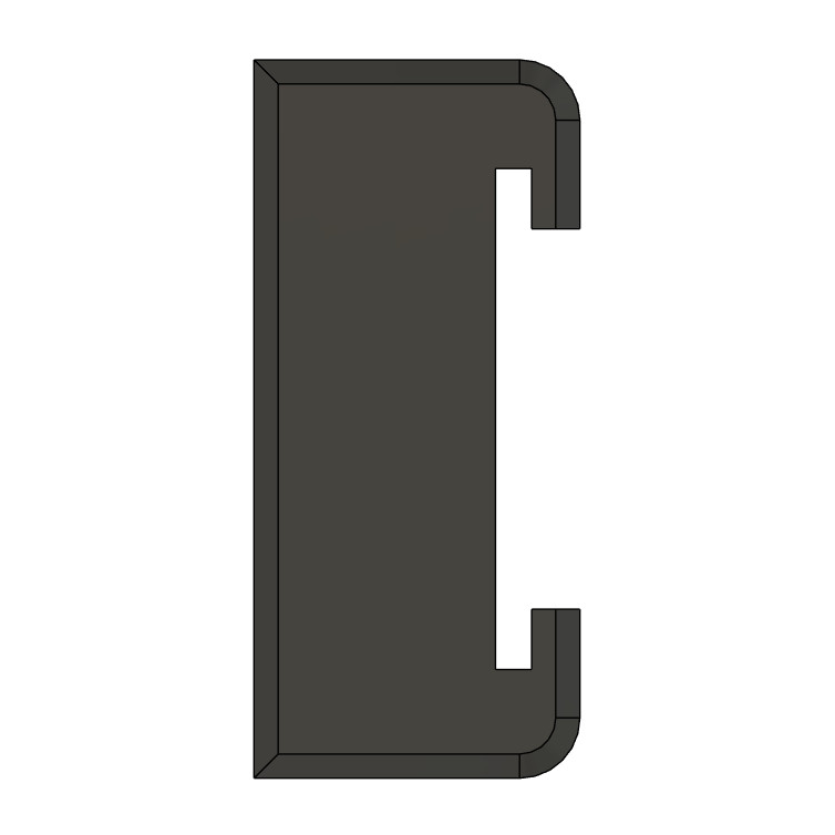
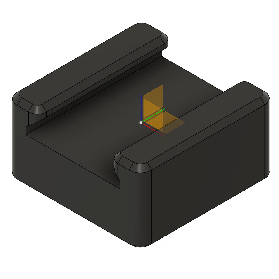
Let’s start with the profile of the light itself. I idealized it as a rectangle with a half-circle on top. It’s close enough, and some calipers get me an idea of where I need to accommodate. In the image above, the dashed lines are this idealized cross-section of the COB light strip. I know my Mk3 can handle a straight angle of 40 degrees, the other part is that I wanted to make sure there was enough meat to make sure it was holding the FPC securely enough while also not blocking the light. This did take a couple iterations to get just right. Lastly, I design my measurements around the layer heights I’m expecting to use (in this case, 0.2mm).

The magnet pocket was pretty simple. I could’ve designed it tighter for more of a press-fit, but opted to keep it wider and rely on CA glue. This pocket will be facing down, so the “ceiling” will have an overhang. It’s only an 8mm diameter magnet, so this should be an easy bridge.
That’s really about it. Slap a couple layers of chamfers (0.4-0.6mm in this case), round the perpendicular corners for the aesthetics, throw it at the printer. I did another variant that used 6×2 magnet, but bed adhesion was poor since everything scaled around the magnet size itself.
I posted the final design here on Printables.com with parameters for printing.

I had another variant that was intended to print long way up (vertical, I called it) that was aimed at making it a little more low profile, but I didn’t want to fiddle with the slot sizing. The oblong shape for the magnet pockets is kinda fun though.